
Sheeted Clastic Dikes in the Megaflood Region
Updated: Aug 26
Sheeted Clastic Dikes in the Megaflood Region, Washington, Oregon and Idaho
Skye W. Cooley
Cooley Geoscience | Mission Valley, MT
Clastic dikes in the Channeled Scablands of Washington, Oregon, and Idaho are vertically-sheeted wedges of silt, sand, and gravel filled from above. They are most numerous and best developed in slackwater deposits (Touchet Beds), but also found in coarser grained flood deposits that contain significant silt. For this study, I collected width measurements and sheet counts from >3000 dikes at >300 sites along the floodway between Priest River, ID and The Dalles, OR. All dikes exhibit identical characteristics and are sourced in flood-laid sediments. I interpret the dikes as sediment-filled hydraulic fractures (flood injectites) that grew incrementally in length and width during floodwater-loading events during the Pleistocene. This interpretation is supported by numerous lines of evidence including the source of fill material, taper direction, and crosscutting relationships with dated tephras, paleosols, and older bedrock. The dikes are not liquefaction features, feeder conduits to sand blows, or other soft sediment deformation features triggered by seismic shaking (i.e., seismites). They are neither larger nor more numerous near active Quaternary faults. In fact, evidence of liquefaction in the Channeled Scablands is rare, despite its transection by more than a dozen faults of the Yakima Fold Belt. Instead, dike size, abundance, and complexity appear primarily controlled by grain size, sediment thickness, and location within the floodway. The largest dikes occur in thick, silty slackwater sequences near the deepest flood channels. Analogous wedge-shaped dikes with sheeted fills are found in marine turbidites, subglacial tills, and sediments overridden by lahars - substrates subjected to rapid sedimentation and repeated loading.

Definition
The term "clastic dike" is a general term that describes thin, sheet-like intrusive bodies of sediment that crosscut layering, whether in unconsolidated sediments or bedrock.
Types of Clastic Dikes
More than 400 articles on clastic dikes have been published since the early 1800s. The literature describes dikes formed by liquefaction (Fuller, 1912; Obermeier, 1998), injection (Jenkins, 1925; Hardie, 1999; LeHeron and Etienne, 2005; Hurst and other, 2011; Ravier and others, 2015), release of volcanic fluids and gasses (Diller, 1890; Gonzales and Koch, 2017), meteorite impact (Kriens and others, 1999; Huntoon and Shoemaker, 1995; Buchner and others, 2022), tectonic extension (Haluszczak, 2007), mass wasting (Winterer and others, 1991), diagenesis (Maher and Persinger, 2023), syneresis (McMahon and others, 2020), desiccation (Lawler, 1923), and freeze-thaw action (Pewe, 1959; Demoulin, 1996).
Classifying Soft Sediment Deformation
A clastic dike is a type of soft sediment deformation feature (SSD). Various classification systems for SSD devised to help aid in interpretation of features in the field have been developed (Potter and Pettijohn, 1963; Dzulynski and Walton, 1965; Nagtegaal, 1965; Hyashi, 1966; Dionne, 1974; Lowe, 1975; Allen, 1982; Mills, 1983; Owen, 1987; Guirard and Plaziat, 1993; Collinson, 1994; Greb and others, 2002; Jolly and Lonergan, 2002; Wheeler, 2002; Obermeier and others, 2005; Castilla and Audemard, 2001; Montenat and others, 2007; Van Loon, 2009; Hurst and others, 2011; Owen and others, 2011; Waldron and Gagnon, 2011; He and Qiao, 2015; Shanmugam, 2017; Alsop and others, 2019; Zhong and others, 2022. However, all of the systems present inconsistencies, which frustrates the user and thwarts widespread adoption. The terminology surrounding clastic dikes can be particularly confusing, as most articles describe a handful of features exposed in some local outcrop without much perspective on dikes described elsewhere. To date, no system captures the full menu of sedimentary dikes in the geologic record and few provide clear rules of thumb for determining the origin of a dike if more than one potential trigger exists. What's needed is an illustrated compendium of clastic dikes that standardizes terminology, addresses common questions, offers guidance to those working with ambiguous features, and provides numerous examples from dozens of locations around the world. I'd be happy to author one for pay.
Avoid Splitting
The main problem with classification systems is they unnecessarily encourage us to become splitters. The temptation to begin delineating one type of dike from another based on perceived differences - especially when your project is in its infancy - must be resisted. It is unlikely that multiple mechanisms conspired to produce different types of dikes of the same age in your field area. Don't be like Karl (Fecht and others, 1999). Pick one mechanism and stick with it for as long as possible.
Six Main Types of Clastic Dikes
Liquefaction Conduits - Dikes and pipes formed by the upward escape of pore water and sediment toward the ground surface. Seismic shaking is often the trigger. Shaking reduces grain-to-grain contact, induces consolidation, and increases pore fluid pressure that leads to their escape as dikes. Water and sand ventdd at the surface produces cone-shaped edifices called sand blows or sand volcanos. Example: Sand blow region near New Madrid, MO.
Hydraulic Fracture Fills - Loading-triggered fractures that open, propagate, and fill with sediment in a pressurized environment. Fracture propagation initiates when fluid pressure exceeds the resistance of the confining material (fluid pressure > fracture toughness). Hydraulic fractures are often triggered by rapid overloading by glaciers, debris flows, lahars, turbidites, or megafloods. Example: Sand injectites in the Panoche Hills, CA.
Passive Infill Structures - Subaerial fractures formed in brittle bedrock or frozen soils that fill with loose material that is washed in by water, blown in by wind, or collapsed in by gravity. Surface fractures may be the result of mass wasting (lateral spreads, slides), thermal contraction (freeze-thaw action), desiccation (drying), or extension (joints, faults, crests of folds). Examples: Permafrost of Arctic Alaska and coal mines near Kleszczow, Poland.
Volcanic-Phreatic Dikes - "Pebble dikes" are breccia-filled dikes that form by the rapid escape of volatile gasses and fluids through fractured rock. Pebble dikes are commonly ore-bearing and associated with hydrothermal systems (i.e., contact aureoles near plutons, plumbing systems of ancient hotsprings, and phreatic vent complexes). Example: Mining districts of the High Rockies.
Syneresis Cracks - Subaqueous shrinkage cracks that fill with sediment, authigenic minerals, or both. Common in shallow, clay-rich marine deposits and certain lacustrine sequences. Syneresis dikes are often long, thin, and filled by materials available nearby. An excellent overview is provided by McMahon and others (2020). Example: White River Badlands, SD.
Impact Injections - Shock waves and intense heat generated during meteorite impacts can trigger the temporary fluidization and injection of sand into the surrounding bedrock. Impact dikes, most often of sandstone, commonly radiate outward from the impact location and contain shocked grains. Example: Upheaval Dome, UT.
Previous Work
The earliest reports on clastic dikes date to the 1800s (Strangways, 1821; Murchison, 1827; Darwin, 1834; Dana, 1849; Gilbert, 1880; Diller, 1890; Cross, 1894). Olaf P. Jenkins (1925) authored the first report on clastic dikes in the Channeled Scablands, specifically those in the Touchet Beds near Walla Walla, WA. A number of similar reports on dikes in slackwater deposits exposed elsewhere in the region were published soon after (Lupher, 1940, 1944; Black, 1979; Woodward-Clyde Associates, 1981). Reports containing measurements, dike distribution maps, and examples of dikes in formations other than the Touchet Beds came next (Alwin and Scott, 1970; Cooley and others, 1996; Neill and others, 1997; Fecht and others, 1999; Ward and others, 2006). While numerous authors have speculated on the origin of clastic dikes in the Touchet Beds (Flint, 1938; Newcomb, 1962; Bingham and Grolier, 1966; Jones and Deacon, 1966; Beaulieu, 1974; Carson and others, 1978; Shaw and others, 1999; Pritchard and Cebula, 2016; Reidel and others, 2021), few support their assertions with measurements, maps, or models. Fresh ideas have been slow to emerge. Articles by Smith (1993), Pogue (1998), and Howard and Pritchard (2020) offer a refreshing departure from this trend.
Omitted or Ignored
Despite their ubiquity in Missoula flood deposits, clastic dikes are not shown in several important descriptions of classic Scabland outcrops (Waitt, 1985; Smith, 1988a,b; Lindsey and others, 1996; Benito and O'Connor, 2003; Sweeney and others, 2017). Some authors have told me, off the record, that they avoided them on purpose because the dikes complicated their work, focused primarily on the stratigraphy.
Proposed Origins of Dikes in the Channeled Scablands
Six origins for clastic dikes in the Channeled Scablands have been proposed: Earthquakes (Jenkins, 1925), ground ice (Lupher, 1944; Alwin and Scott, 1970), desiccation (Grolier and Bingham, 1978), mass wasting (Brown and Brown, 1962; Baker, 1973; Cooley and others, 1996), dewatering (Newcomb, 1962), and hydraulic fracture (Pogue, 1998). A dubious seventh, “multigenetic” (Black, 1979; Fecht and others, 1999), suggests the dikes formed by a combination of processes. Cooley (2015) provides a concise summary of the arguments for and against each hypothesis.
Literature Review
The PDF linked below contains a list of all (or nearly all) articles that mention clastic dikes in the Channeled Scabland. Commentary on and quotes from each is also provided.


This Study
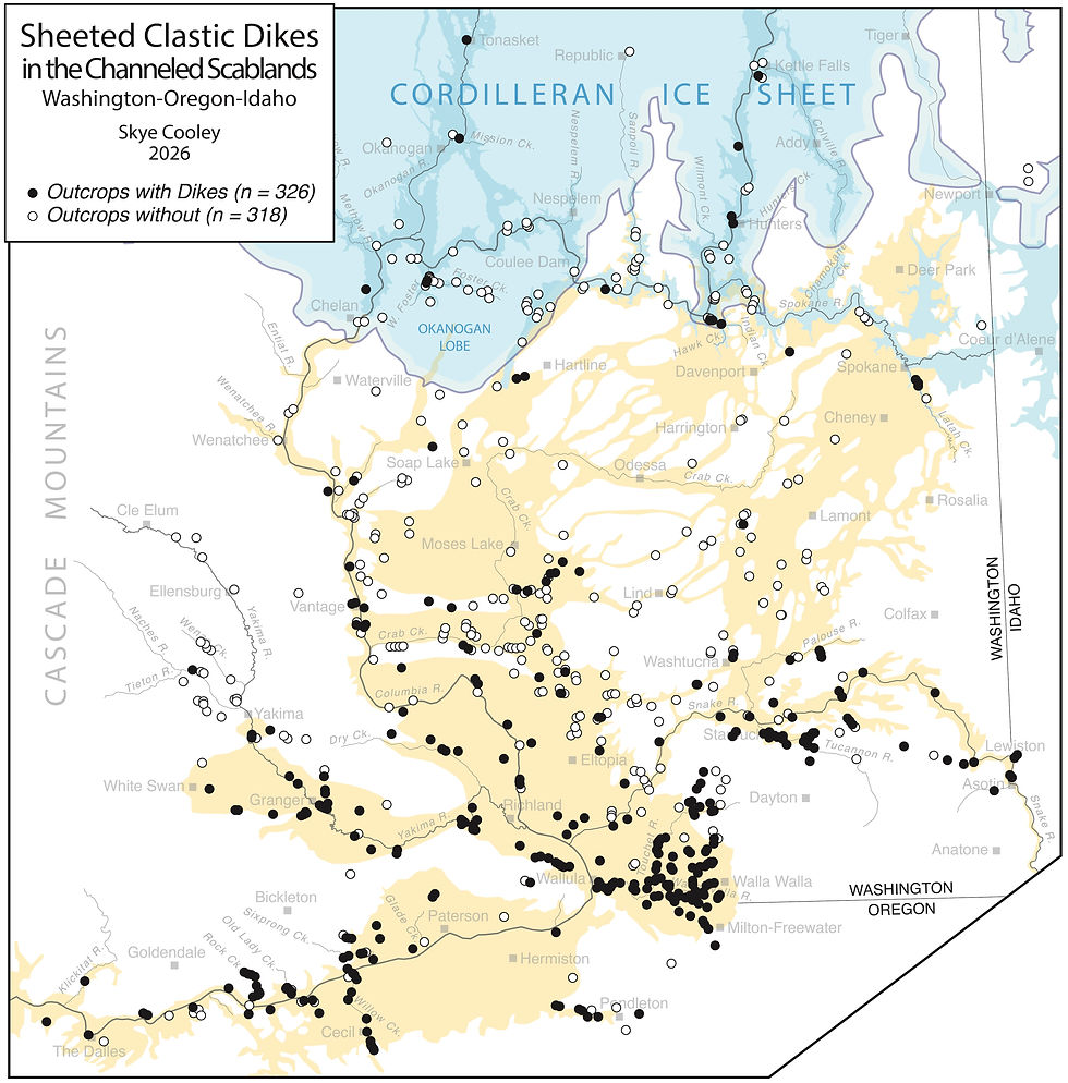
I searched for clastic dikes in unconsolidated sediments, partially-lithified sediments, and flood-scoured bedrock exposed along roads, streams, rail lines, and escarpments between Priest River, ID and The Dalles, OR. I also surveyed dozens of excavated pits, trenches, and quarries. I traversed the valleys of the Columbia, Snake, Yakima, Spokane, Walla Walla, Sanpoil, Touchet, Tucannon, Umatilla Rivers, and those of numerous tributaries. Thick sections of non-flood sediments at Saddle Mountains, Smyrna Bench, Frenchman Hills, White Bluffs, and Palouse Hills were carefully examined along with dozens of cuts north of the Channeled Scablands. Many roadcuts in Palouse Loess both inside and outside the margins of the floodway were inspected as well as dozens of floodplain exposures of Holocene alluvial fills. Pliocene loess sections at Selah and White Bluffs were checked for dikes. I measured the widths of >3000 dikes at >300 exposures and made vertical sheet counts for >1000 dikes. Field work was conducted between 1995 and 2025 using the same field and data collection procedures. The vertically-sheeted sand, silt, and gravel-filled dikes vary in width and length from place to place, but otherwise exhibit identical characteristics wherever found. The dikes occur only within Ice Age floodways and at elevations no higher than Missoula flood trimlines. All appear to have formed by the same mechanism during the Pleistocene, not before or since.


Dike Distribution
Sheeted dikes are not unusual features in Missoula flood deposits, nor are they confined to fault zones. The dikes are widespread and number in the hundreds of thousands (if not millions), distributed throughout an area exceeding 30,000 km2. Identical dikes are found near Kettle Falls, WA, Salem, OR, and Lewiston, ID, sites separated by hundreds of kilometers. The dikes are not present above the flood elevation maximums (~366m in south-central Washington and higher to the north), nor in sandy, unconsolidated, non-flood sediments beyond the margins of the floodway. No dikes are known to intrude Palouse Loess outside of flood-cut coulees. Dikes are present where loess and flood deposits interfinger (i.e., northern Walla Walla Valley and eastern Pasco Basin). Identical dikes occur in close proximity to mapped Quaternary faults (i.e., Wallula fault zone) and at distances >150 km from them. The dikes are largest, most abundant, and best-developed in the thickest sections of silty slackwater rhythmites (i.e., near Wallula Gap through which all megafloods drained).
Size of Dikes
Dike width ranges from 1 cm to 3 m and length regularly exceeds 10 m. Most dikes measure <15 cm wide, contain fewer than a dozen vertical sheets, and have length-to-width ratios of approximately 40:1. The largest dikes contain >100 sheets and penetrate to depths greater than 50 m. The average width of an individual sheet is around 1 cm with the widest examples around 30 cm. Sills rarely widen beyond 30 cm and tend to be short, often pinching out within a few meters.
Shape of Dikes
Dikes in silt-sand rhythmites tend to be slender (H >> W), while those in coarse sand and gravel are stubby, few in number, and crudely sheeted. Dikes that penetrate bedrock are slender and follow obvious joints. The three-dimensional shape of a dike resembles an axe blade with a curved arris and some volume (i.e., PKN fracture model of Perkins and Kern, 1961; Nordgren, 1972; Belin and Carey, 1997; Rahman and Rahman, 2010). Fracture aperture predictably scales with volume. Dikes taper in the direction fractures propagated, in most cases downward. The 2D shape of a dike's cross section changes depending on where the line of section is drawn (i.e., how it intersects the outcrop).
Strike, Dip, and Orientation of Stresses
When viewed from above, the dikes form polygonal networks, so for the most part, dike strike is random. Dips are also quite consistent, typically just shy of vertical. Most dikes crosscut bedding at angles >70 degrees. Sills are less abundant and are always fed by larger dikes. Most sills form short spurs. Overall, dike and sill orientations are consistent with vertical loading. That is, the maximum principle stress (O1) is vertical. The minimum and intermediate principle stresses are horizontal and nearly equal (O2 = O3). Nearly-equal horizontal stresses explain why the dikes twist about their vertical axes similar to how hydraulic fractures propagate in dyed gelatin (i.e, Ham and Kwon, 2019; Nicolas Espinoza on YouTube, youtube.com/watch?v=3pJgZnPUIYE).
Bedding-plane Slip
Shear offsets across the width of a dike are uncommon. Most fractures opened against O3 or O2 without shear. Stair-stepping and en echelon forms are not common, but where observed, involve many small bedding-parallel slips. Centimeter-scale slips are most common, but larger slips exceeding 10 m are found in places. Low-angle slips appear to be either a mass wasting phenomena or perhaps related to drag imposed by fast-moving currents moving over the stack of rhythmites. I've been able to trace one conspicuous low-angle slip surface for several kilometers through a number of outcrops in the northern Walla Walla Valley.
Polygonal Networks
Burned fields, bladed cutslopes, and dry creek beds expose polygonal dike networks in plan view. Horizontal exposures often confirm crosscutting relationships seen in vertical cuts, but uniquely reveal delicate intertwining that occurs where dikes intersect. Intertwined dikes share fill bands and appear to have grown simultaneously despite having different strikes.
Bedrock Influence
There is no indication that the orientation, abundance, or density of dikes are influenced by joint patterns in the underlying bedrock. Dike injection appears entirely governed by stresses created by megafloods, not from bedrock structure. Columnar joints in the Columbia River Basalt are not mimicked by dikes contained in the overlying flood sediments. Identical dike networks develop atop columnar basalt and unjointed bedrock alike. Where dikes do penetrate the bedrock, however, they follow existing weaknesses - joints, faults, and margins of pillows. Similar behavior is seen outside the floodway, in sand dikes at Fort Rock Lake, OR (Allison, 1953; 1979), for example.
Source of Fill
Sediments that fill the dikes is sourced from Missoula flood deposits. The character of fills is governed by flood energy, therefore resembles local flood facies (slackwater rhythmites, coarse laminated sands, bar gravels). I concur with Lupher (1944), who visualized "currents above the fissures" sweeping sediments into fractures, creating dikes with stratified fills in a range of grainsizes. He also found that "many dikes are traceable to overlying current-bedded sand." While most dikes formed during vigorous flooding, some are sourced in soupy lake-bottom sediments deposited during slackwater stillstands. Dikes originate from the base, middle, and top of floodbeds, positions which correspond to the stages of rhythmite deposition described by Baker (1973) and Smith (1993).
Fills Reflect the Local Geology
The number of clastic dikes in the Touchet Beds far outnumbers those in any other formation. However, a significant number of dikes penetrate sediments of the Miocene Ellensburg/Latah Formation, Miocene-Pliocene Ringold Formation, Miocene-Pliocene Dalles Group (Selah, Chenoweth, etc.), early-middle Pleistocene Palouse Loess (L2, L3), pre-Late Wisconsin gravels, and a Pliocene-Pleistocene fanglomerate-calcrete-loess complex known as the 'Cold Creek unit'. Dike fills contain chips of the local bedrock, grains from sedimentary cover units, and chunks of cemented paleosols in addition to substantial suspended-load material carried from areas upstream. Grains of quartz, plagioclase, and muscovite in sand and silt size fractions are most common. Courser fills are typically dominated by basaltic sand and clasts of mixed lithology. Near the western margin of the floodway, where the quartzite-bearing conglomerates crop out, dike fills contain quartzite clasts. Similarly, along the floodway's northern margin, the dikes contain gruss shed from granitic batholiths in the Okanogan Highlands. Pebbles of felsic volcanics, weathered mafics, various granite rocks, and schist (so-called 'exotic' lithologies) are regularly found in gravelly deposits and dikes. Chunks of cemented loess, calcrete, and cemented cicada burrow 'clasts' are common along the eastern margin of the floodway, where thick deposits of old loess reside. In protected slackwater valleys filled with stacks of slackwater rhythmites, Touchet Bed sediment and loess comprise dike fills.
Do Dikes Parallel Drainages?
Orientation data collected in southeastern Washington reveal some parallelism between dikes and modern stream courses exists (Silver and Pogue, 2002). While sets of stream-parallel dikes can occur locally, other sets in the same outcrops crosscut the trend and cast doubt on the notion that dike orientation is controlled by the orientation of the local stream or the valley it occupies. Plots of strike for large numbers of dikes will always approach random (i.e., polygons).
Sheeting and Growth
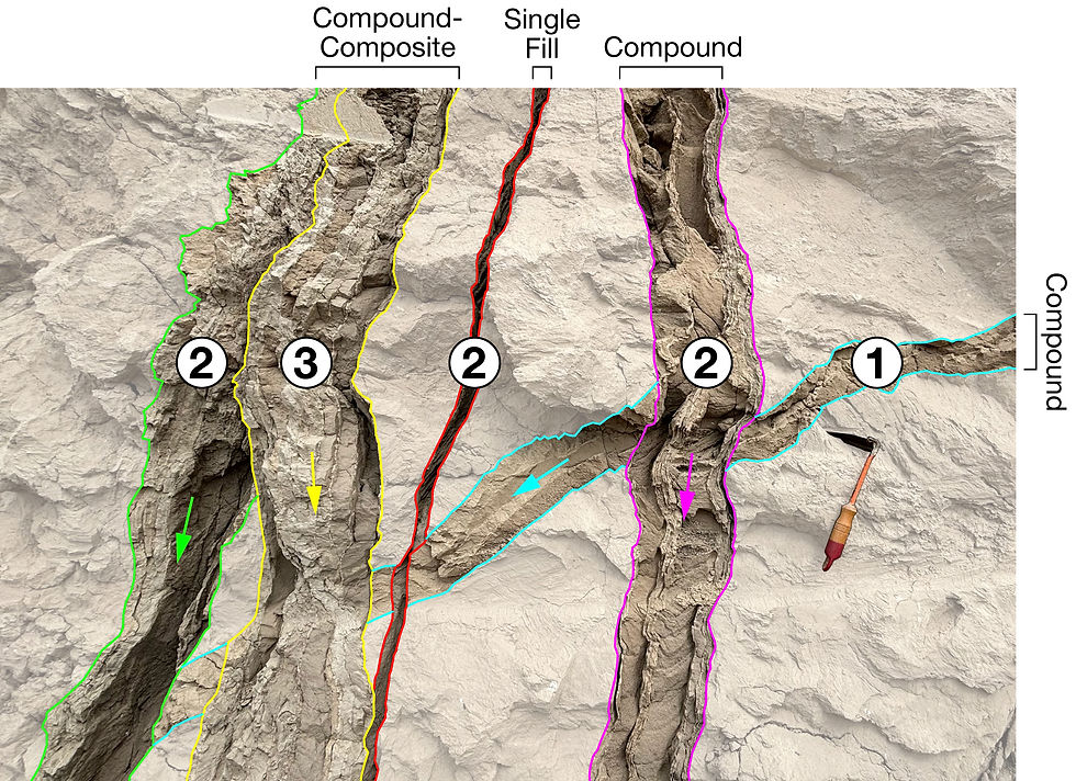
Vertical sheeting developed as dikes widened and lengthened with advance of the crack tip. Sheeting defines three types of dikes: Single-fill, compound, and composite (Hayashi, 1966). Recognition of the three different types is important only because it helps establish whether a dike formed in a single event or grew over time through multiple events. Single-fill dikes contain a single wedge of sediment between two skin walls; a fracture that opened and filled once. Compound dikes contain two or more sheets with skin walls between. In compound dikes, multiple fractures opened and filled during a single diking event. Composite dikes contain multiple sheets injected during multiple diking events (i.e., reinjection over time). In composite dikes, new sheets of sediment intrude older dikes during successive events separated by hiatuses. Each new set of sheets is sourced from a different source with its own grainsize, composition, or sorting characteristics. Each successive crack-and-fill episode has the potential to create sheeted fills that contrast with those that came before.
Stacks Inside Sheets
The filling of vertical sheets occurred in pulses, resulting in the accumulation of coherent 'stacks' of sediment separated by thin silt breaks. These sub-horizontal to dipping skins represent depositional breaks between pulses of infilling. Grainsize and repose angle often change abruptly at silt breaks between stacks. The height of a stack may range from a few centimeters to a few meters.
Age
Field relationships constrain the age of all clastic dikes in the study area to the Pleistocene, between ~1.8 Ma to ~11 ka, the period coinciding with the growth of the Cordilleran Ice Sheet, filling of proglacial lakes, and outburst flooding across Eastern Washington and parts of Idaho, Oregon, Montana, and British Columbia. While a few cemented and truncated outliers exist, the vast majority formed during the last glacial, between 18–14 ka. Many dikes cut the Mount St. Helens Set S tephra (16 ka), but none the Mazama Ash (6.8 ka). No sheeted dikes are known to intrude Holocene alluvium in the study area. Except for crystalline bedrock of the Okanogan Highlands and Belt quartzite in steptoes of the eastern Palouse, the dikes penetrate all formations scoured by megafloods.



Depth of Intrusion
Numerous examples of dikes intruded to depths exceeding 10 m are found in the study area. Borehole logs in the Hanford Plain, where the thickest flood deposits in the Channeled Scabland are found, intersect dikes at depths greater than 50 m. At most sites, dikes pinch out 1-10 m below the surface, which scales with the thickness of flood deposits in most places.
Rate of Injection
Both field evidence and theoretical studies suggest individual clastic dikes form very rapidly, on the order of seconds. Fracture dynamics controls the rate, not the infilling. Fractures open, grow, and fill quickly and do so in jumps. 1-4 m/sec seems a reasonable estimate for the rate for advance of the fracture tip through unconsolidated sediment. Similar rates for the propagation of hydraulic fractures through weak sediments were found by Levi and others (2011) and Davies and others (2012). Diking events appear to last sufficiently long to allow compound dikes to propagate and crosscut one another. A reasonable estimate for the length of a single diking event - the period when flood-load forces exceed substrate resistance - is a few days to a couple weeks.
Skin Walls
Thin silt partitions (skin walls) form the outer boundaries of the dikes and separate internal sheets from one another. Skin walls typically achieve thicknesses of 1–10 mm, sufficient to form an effective seal. A silt skin builds rapidly, progressively thickening into a continuous layer, as pore water migrates out of the fill, through the fracture wall, and into the comparatively drier surrounding material. Leakoff to the formation appears to be the primary dewatering mechanism of Touchet-type dikes. Dikes that penetrate impermeable bedrock, most often basalt, lack outer skin walls but contain internal ones, indicating leakage diverts laterally into adjacent sheets, where it resides temporarily before draining to the formation via fractures. Mostly silt and variable amounts of clay comprise the skins. Muddy sediment that forms dike walls is not injected first, as suspected in some till dikes (Phillips and others, 2013), rather the fines are the finest constituent of the entering slurry that is quickly screened against the walls. Skin building and fracture sealing begin immediately. An analogous process occurs during the formation of concrete slurry walls used in heavy construction, such as trench-type building foundations.
Flutes on Skin Walls
Flutes are created by erosive scour. Their asymmetric shape precisely records the direction of flow. Upward-pointing flute casts ornament the interior faces of skin walls. The flutes adorn the inside surfaces of the outer walls and all faces of interior walls. Fluting unambiguously indicates sediment entered the fractures from the top. The preserved fluting is not subtle or sparse; the forms are obvious and present in nearly all dikes.
Rip-up Fragments in Fills
Fragments of older fills, chips of skin walls, and broken bits of the host material are a significant component of many dike fills. In places where dikes cut white tephras such as the Mount St. Helens Set S tephra, traces of ash are sometimes visible in the fill.
Slickensides
Slickensides, while often observed in dikes from other regions, are generally not present in Touchet-type dikes. Preservation of slicks in unconsolidated sediment is uncommon. In the few cases where I have seen slickensides, the dikes were cemented with CaCO3.
Stratified Fills
Cross-lamination is a conspicuous characteristic of most dike fills, but especially coarse sandy fills. As a turbulent sediment slurry enters an open fracture, it settles and stratifies almost immediately. Stratification develops under Newtonian flow during the brief period when the fracture is open and hydraulically connected to the surface (voluminous water-sediment reservoir). Laminated fills accumulate in open or widening fractures, whereas structureless fills likely record the instantaneous closure of the fracture and the resulting “freezing” of unsettled sediment. Abrupt termination of intrusion following a drop in fluid pressure has also been documented in sand injectites associated with deep-sea fans (Jonk et al., 2010; Dodd et al., 2020). Sheets filled with silt commonly lack clear stratification. But what can appear structureless at first glance often turns out to be subtly laminated after some light work with a soft brush. I disagree with Lupher's interpretation of structureless fills were deposited by wind into open-standing cracks without the aid of water (Lupher 1940, 1944). The field evidence simply does not support the filling of open surface cracks by dry sediment.
Leakoff Halos
Leakoff halos are firm and discolored zones that extend a few centimeters beyond the outer walls of some dikes. Leakoff halos are a product of dewatering consisting of fines that were not screened at the dike wall.
Lumpkins
Lumpkins are bulbous forms on the exterior walls of some dikes formed by leakoff. Leakoff indicates the host sediment during diking was ice-free and drier than fracture-filling slurries (i.e., vadose zone). The Lumpkins were a terrible band from Bellingham.
What causes a dike to terminate?
There are several ways to halt the growth of hydraulic fractures, thus the growth of clastic dikes. Lost of fluid pressure via leakoff to the formation will do it (i.e., fluid pressure, Pf < confining pressure, O3). Barriers and strongly contrasting layers with a high Young’s modulus or strength greater than a fracture's ability to break it can too (i.e., cemented sediment, frozen sediment, hard bedrock). Weak or permeable bedding planes can cause a fracture to branch or become a sill. Increased depth, a proxy for confining pressure, can terminate vertical advance. Reduced injection rate at the top of the fracture can also cause a fracture to close. Rate reduction may result from shallower water (less head pressure) or completed filling of the fracture with sediment.


Dikes in Faulted Sediments
In general, the dikes are not clustered along prominent joint systems or otherwise controlled by bedrock faults. Dikes are found in major fault zones, but in fewer numbers than in areas well away from faults. More often, dikes and local faults interact at the meter scale. Small normal faults that cut unconsolidated flood deposits likewise do not act as a primary control on diking. The dikes far outnumber faults and dip more steeply. Single-fill and thin compound dikes most often cut cleanly through bedded sediments, pioneering new pathways. Where dikes and faults interact, dikes cut faults, faults cut dikes, and dikes follow portions of faults. It is not unusual to find all three relationships in a single outcrop. Rotational slumps in slackwater sediments and in bedrock do seem to influence dike location, size, orientation, and number, at least locally. Bedding-parallel slip is common in slackwater sections, although it is often quite subtle. Small slips (<1 m offsets) that repeat in successive beds produce a stairstepping offset pattern in vertical dikes. Larger slips (>10m offsets) may shift entire packages of strata laterally and truncate the dikes. It is usually possibly to locate and match up the offset portions. Thrust faults are uncommon in scabland deposits and their influence on diking is minor.
Dikes Near Mapped Bedrock Faults
Eastern Washington is criss-crossed by more than a dozen mapped thrust faults associated with the Yakima Fold Belt and other systems such as the Hite Fault (Schuster and others, 1997). Sheeted clastic dikes sourced in glacial-age material intrude folded and faulted basalt flows and interbeds at Umapine, Touchet, Rattlesnake Hills, Horse Heaven Hills, Alder Ridge, Gable Mountain, Cecil, and elsewhere. I disagree with studies, notably Camp and others (2017, Fig. 50) and Reidel and others (2021, Fig 8.), which suggest a causal link between faults and dikes exists. I have traversed most of the sedimentary sections preserved atop the fault-bounded ridges, finding fewer and smaller dikes directly atop Quaternary faults than in sections located many kilometers from them. For example, I observed no sheeted dikes in the 3-25 m-thick Plio-Pleistocene section preserved at the crest of the Saddle Mountains anticline. Similarly, the gullied and fault-bounded Smyrna Bench section contains only a few small dikes, all below the elevation of Missoula flooding. I surveyed 20 km of the 150 m-thick section of Ringold Fm at White Bluffs, finding a few clusters of dikes in sandy Missoula flood deposits and a few isolated dikes in the Ringold. The White Bluffs lie directly along the strike of the Gable Mountain fault. I found very few dikes in scattered exposures at Frenchman Hills and neighboring Royal Slope. Plio-Pleistocene sediments exposed in lower Lind Coulee and in fault trenches near O'Sullivan Dam (West and Shaffer, 1988) are devoid of dikes, though a set of thin dikes cuts a hard, white bed in the Ringold at Othello Canal. No dikes were observed in a 10 m-thick Miocene diatomite exposed near the Frenchman Hills fault and in an active surface mine off the Beverley-Burke Road. No dikes were observed in a 4 m-thick interbed (Miocene overbank deposits) cut by the Arlington-Shutler Butte Fault exposed west of Arlington, OR (more about the ASBF HERE).
Water Table Position During Inter-flood Periods
The presence of silt skins, leakoff halos, rodent burrows, numerous brittle fractures, and minimal wetland soil indicators in the Touchet Bed suggest that a thick, well-drained, and ice-free vadose zone was reestablished each time floodwaters drained from the landscape. The field evidence hints at a wet-over-dry-over-wet condition that promoted brittle fracture in the subsurface. Brittle fractures initiated between the base of the flood and top of the water table served as entry points for hydraulic injection through the vadose zone. I believe the Pleistocene water table fell during inter-flood periods, returning to a position approximating the modern water table. Streambanks then and now reside well below the flat tops of benches composed in modern valleys.
Pristine Preservation
While the Touchet Beds contain clear evidence of recolonization by plants, rodents, insects, and mammoth during the decades-long periods between megafloods (Waitt, 1985; Spencer, 1989; O'Geen and Busacca, 2001; McEachern and others, 2013; Last and Rittenour, 2021), bioturbation was modest overall. Original bedding, often quite fragile, remains intact and pristine nearly everywhere, a strong argument against wholesale reworking. Fine laminae and thin silt walls are nearly always perfectly preserved in dike fills. In contrast to the Palouse loess and most Holocene alluvium, thorough mixing by organisms is rarely found in Scabland deposits.
Subsurface Imaging of Dikes
A few attempts to image the subsurface geometry of individual dikes and large networks using ground penetrating radar (GPR) have been made at the Hanford Site (Murray et al., 2001; Williams and others, 2002; Clement and Murray, 2003; Ward and Gee, 2003; Ward et al., 2006). Radar images prove that the general shape of dikes >1 m wide can be resolved to a depth of about five meters. GPR images show no widening at depth and no connection to buried feeder beds (i.e., dikes are not fed from below).
Dikes as Fast Fluid Conduits?
Sandstone dikes have long been recognized as fast migration conduits for oil, natural gas, and ore-bearing fluids (Murchison, 1827; Rickard, 1903; Anderson and Pack, 1915; Jenkins, 1930; Braccini et al., 2008). In fact, sand injectites are targeted by drillers in offshore oil fields specifically for their high permeability. Likewise, in hard rock mining districts (i.e., Colorado Mineral Belt), sedimentary dikes that often parallel bedrock fracture systems are known to concentrate economic minerals such as Au, Ag, Pb, Cu, Zn. Despite the well-established conduit behavior of sand dikes in shallow terrigenous sediments, offshore fan-turbidites complexes, and bedrock mining districts worldwide, Hanford scientists think that the thousands of sand, silt, and gravel-filled dikes beneath the Hanford Nuclear Site function differently. According to Murray and others (2007), the dikes do not quicken vertical transport of chemical waste fluids leaked from storage tanks into the deeper subsurface and actually retard lateral flow in the vadose zone. Unsurprisingly, the findings of the Murray study contrast with reports by scientists at other U.S. Department of Energy facilities, the rest of the geologic literature, physics, and common sense (Reichert and Fenimore, 1964; Pollard and Aydin, 1988; Finfrock, 1994; Caggiano, 1996; USDOE, 1996; Faybishenko et al., 2000; Serne et al., 2002, 2004, 2020; Bjornstad and Lanigan, 2007; Fang and Mayes, 2007; Gee et al., 2007; Reidel and Chamness, 2007; Rockhold et al., 2015; Springer et al., 2017). The lightning just ain't distributed right.




Liquefaction in Eastern Washington?
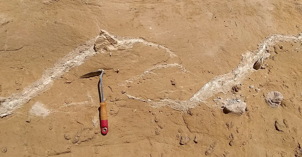
To date, no significant liquefaction has been identified in more than a dozen trenches excavated across young fault scarps in the Channeled Scabland. Trenching reports are listed here and briefly reviewed below.
Ahtanum Ridge-Burbank trench near Yakima, WA (Bennett and others, 2016).
Horned Lizard trench in the western Boylston Mountains, WA (Barnett and others, 2013).
Toppenish Ridge trenches above Pumphouse Rd, WA (Campbell & Bentley, 1981; Campbell & Repasky, 1995; Repasky and others, 1998).
Ahtanum Ridge (Repasky and others, 1998)
Wenas Valley trench, WA (Sherrod and others, 2013).
Saddle Mountains trenches at Smyrna Bench, WA (Bingham and others, 1970, Plates 4,5,6).
Buroker roadcut southeast of Walla Walla, WA (Farooqui and Thoms, 1980; Foundation Sciences, 1980).
Lower Lind Coulee trenches east of O'Sullivan Dam, WA (GEI/West & Shaffer, 1988).
Gable Mountain trenches at the Hanford Site, WA (Bingham and others, 1970; Golder Associates/PSPL, 1982).
Spencer Canyon trench near Entiat, WA (Sherrod and others, 2015).
Finley Quarry west of Wallula Gap, WA (Sherrod and others, 2016; Coppersmith and others, 2014).
Starthistle trench east of Wallula Gap, WA (Angster and others, 2020, 2023; Mahan and others, 2022).
Kittitas Valley trench, WA (Huddleston, 2022; Dr. Walter Szeliga, personal and written communications, 2023).
Gate Creek trench near The Dalles, OR (Bennett and others, 2021; Madin and others, 2021).
Gales Creek trenches near Portland, OR (Horst and others, 2021; Redwine and others, 2017).


Finley Quarry - Two investigations claim to have found liquefaction features in sediments near Wallula, WA (Wallula Fault Zone). The first is Finley Quarry located west of Wallula Gap (Sherrod and others, 2016). Several conspicuous vertical, rubble-filled fractures were initially investigated by Kienle (Foundation Sciences, 1980). In an accompanying report, Farooquoi and Thoms (1980) observed "thin clastic dikes of sand" and "clastic dikes of very light terracotta-colored silt" intruding zones of fault breccia in the older basalt. Rockwell Hanford Operations also opened a 310 m-long trench in 1977, finding sheared and brecciated basalt, but no conclusive evidence of deformed Quaternary deposits (Jones and Fecht, 1977; Gardner, 1977). Reinvestigation of faulting at the quarry by USGS (Sherrod and others, 2016) lead to discovery of an old clastic dike cutting two beds of silt-pebble diamict. Sherrod misinterpreted it as a liquefaction feature formed in response to strong shaking. The beds hosting the dike are silty flood deposits identical to those exposed nearby in large roadcuts along Hwy 397 (i.e., reworked loess not wind-deposited silt). A team of co-investigators disputed the interpretation in a separate report (Coppersmith and others, 2014).

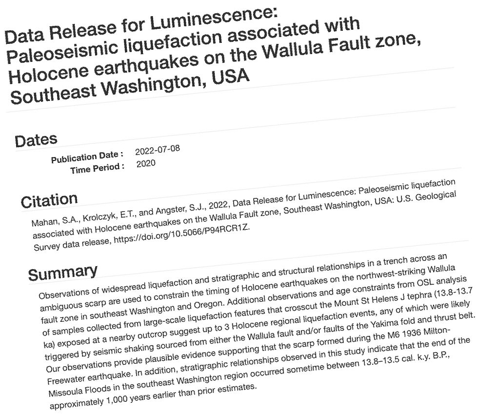
Starthistle Trench - Angster and others (2020, 2023) reported finding liquefaction features in Holocene loess east of Wallula Gap. The set of small, blobby structures that occur within and below the modern soil profile post-date the 13 ka Glacier Peak G tephra. I note several problems with their trench log interpretations. a.) The surface lineament they targeted for trenching is actually an old ranch road, not a fault scarp. Remnants of old pavement are clear in the trench wall and the old road network appears in historic aerial photographs (see THIS POST). b.) Touchet Beds that underlie the "liquefied" loess remain undeformed, a logical flaw that invalidates their argument. c.) A windblown origin for beds at Starthistle interpreted as "loess" may be incorrect; the bed might be a water-laid silt (loess reworked by water). d.) The blobby features themselves are anomalous, yet they bear no resemblance to the "liquefaction dike" just across the river at Finley Quarry (Sherrod and others, 2016) or features associated with thousands of sand blows described near New Madrid, MO (i.e., Obermeier, 1990, Fig. 4 and 22). Though numerous nearby roadcuts and streambanks expose the same sediments, none contain blobs. I believe the blobs are local, minor anomalies related to soil forming processes that have been misinterpreted by Angster as earthquake-induced liquefaction. They might krotovina, or features produced during dewatering after a heavy rainfall event, or any number of other things. Wild claims of "widespread liquefaction" caused by shaking along the Wallula Fault Zone (i.e., Mahan and others, 2022) are entirely unsupported by observations made at the Starthistle trench or Finley Quarry. Strange that the USGS team did not visit the nearby Wallula Bluffs (<3 km away), where repeated fluidization in successive Touchet Beds is well displayed. There, deformed and undeformed bedding (silty upper portions, sandy lower portions) alternate through a stack of about a dozen "late" rhythmites. Deformation is tied to grainsize and deposition during a certain flood stage, not seismic shaking (see Wallula Bluffs stratigraphy figure below).


Gable Mountain Trenches - Several trenches were opened across two thrust faults at Gable Mountain on the Hanford Site by Golder Associates (Bingham and others, 1970; Golder Associates/Puget Sound Power and Light, 1982). The South Fault displaces Miocene Pomona and Elephant Mountain basalts and the Rattlesnake Ridge interbed by about 15 m. Unfaulted Missoula flood deposits (Hanford Fm) overlie the fault. The Central Fault displaces the Rattlesnake Ridge by 55 m, but the Hanford Fm by only 6 cm (Reidel and others, 1992, p. 43-44). No liquefaction was found in trenches at Gable Mountain. A wedge-shaped clastic dike filled with flood-laid sediment exploits a weak zone of brecciated basalt (Trench log GT-2 in Reidel and others, 1992, Figure 39, p. 45). The Late Pleistocene dike post-dates the fault breccia.
Lind Coulee Trenches - Trenches were opened across the Lind Coulee Fault in the 1980s by consultant Michael West on behalf of dam managers at the U.S. Bureau of Reclamation (West and Shaffer, 1988; Shaffer and West, 1989; Geomatrix Consultants Inc., 1990). The fault, an eastern extension of the Frenchman Hills thrust, places Miocene Roza over Pleistocene Palouse loess. Trenches near the shoreline of Lower Crab Creek/O'Sullivan Reservoir revealed relationships similar to those at Gable Mountain, namely that clastic dike injection post-dated faulting. Initially, crews believed they had uncovered a colluvial wedge and Missoula flood sands "injected into the fault zone", but their interpretation changed as trenching proceeded. Ultimately, the GEI team found,
...no evidence of shearing, tectonic displacement or colluviation characteristic of surface fault rupture. The [flood-deposited] sands along the shear plane appear to have been injected hydraulically along the plane rather than dragged along it...the sand was injected hydraulically from the top...The last surface fault displacement, therefore, occurred before 40 to 50 Ka...Similar injection of flood sands along shear planes was noted in fault trenches excavated on Gable Mountain (DOE/Westinghouse, 1987b).
Toppenish Ridge Trenches - Four trenches were opened across splays of the Toppenish Ridge Fault by Ted Repasky and Newell Campbell in the 1990s (Campbell and others, 1995; Repasky and others, 1998). Trenching, GPR surveys, hammer seismic surveys, and age dating at the site were supported by USGS in partnership with the Yakama Indian Tribe. No liquefaction features or clastic dikes were observed in the trench walls. The latest movement on the fault was estimated at 500-700 years BP, consistent with previous reports (Campbell and Bentley, 1981). Seventeen kilometers along the ridge to the east, two gravel pits straddle the same fault, exposing both hanging wall and footwall strata. The upper pit (hanging wall) is located <200m from the fault at an elevation of 265-295 m. There, a thick, partially-indurated, quartzite-bearing Miocene conglomerate dips steeply south into the fault. No liquefaction features or clastic dikes were observed in the tilted beds. At the lower pit, located to the south and some 40 m lower, the quartzite-bearing Snipes Mountain Conglomerate is nearly flat-lying and capped by light gray Touchet Beds. Several light gray clastic dikes crosscut the darker conglomerate. Touchet Beds are the unambiguous source for all dikes exposed in pits off Tule Road. They are filled from above, pinch downward, and show no connection to a liquefied source below. The dikes post-date deposition of the conglomerate and most, if not all, of the tilting.

Smyrna Bench Trenches - Trenches excavated through loess, basaltic fanglomerate, calcic paleosols, and sheared basalt along the north flank of the Saddle Mountains revealed no liquefaction features or clastic dikes (Bingham et al., 1970). A few conspicuous vertical features noted in field sketches are loess-filled tension cracks, not injection structures. The loess-filled openings are gaps between broken blocks of bedrock. According to project geologist John Bingham, "Some of these are filled with loess; others contain fragments derived from the walls of the crack. Several of the cracks show some stratigraphic offset, but no gouge zones or slickensides". The geology of Smyrna Bench is described in reports on the Saddle Mountains (Twiss, 1933; Jahns, 1966; Grolier and Bingham, 1978; Campbell, 1979; Reidel, 1978, 1984, 1988; ARCO, 1982; West and Shaffer, 1988; West and others, 1989, 1996; West, 1997, 1998; Reidel and Fecht, 2002; Tincher and Reidel, 2009; Hart and others, 2012; Staisch and others, 2016, 2018).
Wenas Creek Trenches - Scarps in the Wenas Creek Valley, identified from lidar imagery, were trenched by USGS in 2009. Two trenches located 5 km apart were opened in alluvial fan deposits and revealed several small faults offsetting the bedrock, cover sediments, and soils. No liquefaction features or clastic dikes were observed.
Buroker Roadcut - A small reverse fault exposed along Russell Creek Road six miles east of Walla Walla was investigated in the late 1970s by Rockwell (1979), Foundation Sciences (1980), and Farooqui and Thoms/Shannon & Wilson Consultants (1980) on behalf of Washington Public Power Supply System. A sketch by Foundation Sciences shows the fault offsetting Miocene basalt of the "Dodge" flow (lower Wanapum), post-basalt stream gravel, and oxidized Palouse loess with a caliche stringers. Younger gray and dark brown loess units above are not cut by the fault. Clastic dikes are indicated in the Palouse loess, but they do not appear in the sketch. According to Swanson in Rockwell (1979), the fault cuts "fluvial gravels and an older loess, but does not deform overlying young loess." A different interpretation of the same roadcut is provided by Farooquoi and Thoms (1980). Their Figure 11 shows the fault offsetting weathered Miocene basalt and reddened Palouse loess. Throw on the fault is 56 cm. Holocene loess is not cut by the fault. The report identified no clastic dikes, but notes some "fractures are lined with caliche". I was unable to locate clastic dikes in the roadcut during a visit in 2026.
Boylston Mountains Trenches - Scarps identified from lidar imagery along Johnson Creek and Park Creek, were trenched by USGS in 2010 (Barnett and others, 2013). The Horned Lizard trench exposed two colluvial wedges atop a prominent fracture. A buried soil consisting of dark brown, silty-clay with prismatic structure separates the two bodies of colluvium. Two episodes of fault movement were interpreted, separated by a length of time sufficient for a soil to accumulate. No liquefaction features or clastic dikes were observed.
Arlington-Shutler Butte Roadcut - The Arlington-Shutler Butte Fault is well exposed along I-84 west of Arlington, OR. A wide road shoulder for the east-bound lanes provides access to the large, clean, vertical roadcut. The oblique-normal fault cuts Miocene basalt and a sedimentary interbed. The fault is truncated by a boulder gravel deposited by the Missoula floods. The unfaulted flood gravel fills a swale cut right across the fault. The fault is believed to have last moved during early to middle Pleistocene time (<780,000 years). Its length indicates it is capable of producing <4.0 magnitude quakes. The fault strikes northwest across the Columbia River, connecting Jones Canyon with Old Lady Canyon. No clastic dikes or liquefaction features were observed during a visit in 2024.
Ahtanum Ridge Trenches - A Ted Repasky and Newell Campbell study just south of the Yakima Valley. No liquefaction features or clastic dikes were observed. Limited information exists on this investigation.
Gate Creek Trench - A study by Ashley Streig (PSU) and Scott Bennett (USGS) on a portion of the Mt. Hood Fault Zone in Oregon. An offset of 1.5 m was observed and a last-movement age of ~1000 years was determined from carbon dates on charcoal. No liquefaction features or clastic dikes were observed. The site lies well outside the Pleistocene floodway.
Kittitas Valley Trenches - The Dead Coyote and Bitterbrush trenches were excavated by Dr. Walter Szeliga and student Craig Huddleston across a strand of the Dead Coyote Fault northeast of Ellensburg (Huddleston, 2023). The project built on a previously unsuccessful attempt to assess the history of the north-dipping reverse fault by USGS/Brian Sherrod (c. 2022). The scarp, visible in lidar imagery, crosses Miocene basalt, old fan remnants, and Quaternary gravels of the Reecer and Naneum fans. Trenching exposed small shear zones that offset fan conglomerates, colluvium, and a buried soil. Two rupture events occurred since about 470 ka. An undeformed colluvial unit and the modern soil overlie the fault. No liquefaction features or clastic dikes were observed.
Spencer Canyon Trench - The Spencer Canyon trench was opened across a prominent scarp observed in lidar imagery near Entiat, WA (Sherrod and others, 2015; Brocher and others, 2017; Brocher and others, 2018; Sherrod and others, 2021). The scarp is believed to have formed during the 1872 North Cascades/Chelan quake (>6.5 M). Bedrock at Spencer Canyon is not Columbia River Basalt, but older crystalline rock of the North Cascades. It is unclear if the fault is part of the Yakima Fold Belt or an older set of faults in the older bedrock. Vertical structures shown in sketches of the trench wall are sediment-filled root casts. No liquefaction features or clastic dikes were observed.
Holocene Dikes West of the Cascade Divide
Floodwater spilling out of the Columbia River Gorge ponded in the Willamette Valley, blanketing its floor with sand and silt and from Portland to Eugene. Ice-rafted boulders of "granite and schist" were first noted by Diller (1896) and later more lithologies were mapped throughout the basin (Bretz, 1919; Allison, 1935; Minervini and others, 2003).
While the Willamette Silt does contain clastic dikes, they are far fewer than in Columbia Basin some 350 km upstream. PhD student Jerry Glenn documented a few sheeted dikes at his River Bend and Irish Bend sites near Corvallis, OR (Glenn, 1965). Dr. Ira Allison (Allison, 1978, Figure 14) photographed a clastic dike cutting slackwater rhythmites near St. Paul. Dikes exposed in the basement of the Oregon State Capital Building at Salem were sent to me by Ray Wells in 2012. Photos of dikes exposed in highway excavations near Portland were taken by Ian Madin and also shared with me in 2014.
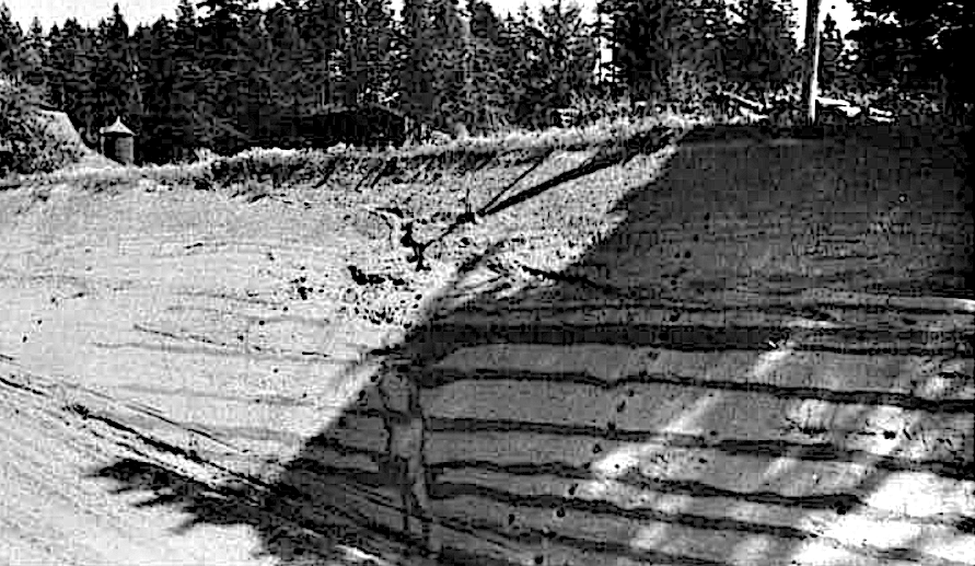
Thurber and Obermeier (1996) reported finding 16 clastic dikes at 7 sites along the lower Calapooia River, a tributary to the Willamette River. The largest features measured 10 cm wide x 5 m long. They attributed the dikes to liquefaction triggered by a Holocene earthquake. No specific fault or event was identified. The copy of the Calapooia report that I obtained contained no photos of dike fills or sketches detailing field relationships between the dikes and the sediments they intrude. Consultant John Sims (2002) reviewed the report, concluding Thurber and Obermeier's data set was too small to support their interpretation,
The limited area surveyed by [Thurber and Obermeier] in the Willamette Valley does not allow for a high level of confidence in determining if the features result from large subduction events or local intracrustal events. The age of the structures is somewhat in doubt as few radiocarbon dates are available for the host deposits and Thurber and Obermeier (1996) do not report any radiocarbon dates as part of their study. They also do not mention any evidence for liquefaction in post Pleistocene deposits of which there are many in the banks of the Willamette River and its tributaries. Thus, with incomplete coverage and lack of dating of paleoliquefaction features, the question of source zones is moot. Earthquake source determination can only be addressed with broader coverage of liquefaction features and better age data to constrain timing of events and to allow regional correlations of liquefaction features. In addition, we need a more complete picture of the size distribution of similar-aged features for the purposes of evaluating the magnitudes of prehistoric earthquakes.


Obermeier and Dickenson (2000), working in the nearby Columbia River Valley west of the Cascade divide, found "relict liquefaction features" in low shoreline bluffs of sandy islands between Astoria, OR (Marsh Island) and Kalama, WA (Bonneville Dam) and in cutbanks of 10 tributary streams in the Hood River area. The thickest dikes they measured were 30 cm wide, on par with dikes in Missoula flood rhythmite sections I have documented in side canyons east of the divide (i.e., Sixprong, Glade, Rock, Old Lady, Arlington, Chenoweth, Willow, etc.). The authors attributed the dikes to lateral spreading, hydraulic fracturing, ground shattering, and warping triggered by earthquakes. Similar investigations by USGS and DOGAMI were conducted in the Columbia gorge (Obermeier, 1993; Peterson and Madin, 1997; Atwater, 1994) and contain some of the same information, which has created a record that is a bit confusing.
Atwater (1994) and Takada and Atwater (2004 + Appendix A Supplement) describe sandy riverbank sediments in the lower Columbia River gorge deformed by the 1700 AD Cascadia earthquake. They note Holocene-age dikes filled with sand and sills that,
...mostly follow and locally invade the undersides of mud beds. The mud beds probably impeded diffuse upward flow of water expelled from liquefied sand. Trapped beneath mud beds, this water flowed laterally, destroyed bedding by entraining (fluidizing) sand, and locally scoured the overlying mud.
Peterson and Madin (1997) and Peterson and others (2014) describe unsheeted sand dikes and sills in Holocene overbank muds at sites near the mouth of the Willamette River and in bluffs along Pacific beaches near the mouth of the Columbia. They also interpret the dikes as features triggered by the 1700 AD event. A field guide was prepared for a Friends of the Pleistocene outing (Peterson and others, 1993).
All of the dikes and sills described by Atwater (1994), Thurber and Obermeier (1996), Obermeier and Dickenson (2000), Sims (2002), Takada and Atwater (2004), and Peterson and others (2014) are fluid escape structures that formed in wet floodplain deposits west of the Cascade divide. They do not resemble the sheeted, wedge-shaped injection dikes found in scabland deposits. While a seismite interpretation is reasonable, none of the reports clearly document a source bed for the dikes and I wonder if some sections they called Holocene are actually Pleistocene. Perhaps a deeper dive into their unpublished field notes would clarify.
![Holocene liquefaction dikes in the lower Columbia gorge. Caption for Figure 13b in Atwater (1994) reads, "Dikes with raised edges at upper Wallace Island [near Longview, WA]...The dikes transect mud beds that extend parallel to shoreline." This is the same dike pictured in Peterson and Madin (1997, Fig. 11b) and probably the largest example seen by all parties involved. Guessing that's Atwater's shovel in the photo.](https://static.wixstatic.com/media/13658e_1758b11711a24cd4a333e0c022520cfe~mv2.png/v1/fill/w_806,h_597,al_c,q_90,enc_avif,quality_auto/13658e_1758b11711a24cd4a333e0c022520cfe~mv2.png)

Clastic Dikes and Seismic Hazard Maps
Clastic dikes are commonly observed in earthquake-prone regions of the world and are often highlighted in post-quake damage assessments (i.e., Walsh and others, 1995). Systems for describing sediments deformed by strong shaking have matured over the past century thanks to dedicated staff at USGS, state geological surveys, and consulting firms (McCulloch and Bonilla, 1970; Gohn and others, 1984; Atwater, 1994; Obermeier, 1990, 1992, 1996, 2009; Peterson and Madin, 1998; McCalpin, 2009; Holtzer and others, 2011). Maps of liquefaction features often help geologists delineate the extent of deformation following a large quake. The value of such maps largely depends on the intensity of the field effort (size of the dataset) and experience of the geologist. A small number of measurements or measurements collected within a small area (i.e., one valley or one trench) have low value because they lack statistical power and may not reflect the actual pattern of damage. Misinterpretation of features and field relationships can also be a problem, especially for inexperienced staff or where exposure is poor. The assumption that all clastic dikes form by liquefaction triggered by earthquakes has led many to incorrectly identify features formed by aseismic processes seismites. Investigators should be especially aware of knowledge gaps, their own biases, and those of their managers and editors. Caution and restraint are helpful when interpreting paleoseismic information in the field (Borradaile, 1984; Bonilla and Lienkaemper, 1990; Holtzer and Clark, 1993; Moretti and Van Loon, 2014).

Paleoseismology Community Audits Itself
In 2017, an international conference was convened to review reporting on seismites in sedimentary sequences. Participant emphasized the need for caution (Feng, 2017). It seems “seismite” (Seilacher, 1969; Montenat and others, 2007; Van Loon, 2014) has for some time been assigned too liberally to features of nonseismic or ambiguous origin, making reexamination of "classic" seismite localities necessary. Clear-eyed geoscientists who participated reattributed many features formerly identified as seismites to nonseismic processes, most commonly to rapid sedimentation and loading (Moretti and Van Loon, 2014; Shanmugam, 2016 and references therein). The following quotes capture the feelings of some participants:
Nonseismic events can create structures that are virtually indistinguishable from seismically-deformed sediments, or seismites. Therefore, paleoseismologists must correlate candidate seismites over regions and rule out nontectonic origins before concluding that an earthquake occurred.
– L.B. Grant
A great progress has been made in researches [sic] of soft-sediment deformation structures (SSDs) and seismites in China. However, the research thought was not open-minded. About the origin of SSDs, it was almost with one viewpoint, i.e., almost all papers published in journals of China considered the beds with SSDs as seismites. It is not a good phenomenon.
– Z-Z. Feng
At present, there are no criteria to distinguish...soft-sediment deformation structures formed by earthquakes from SSDs formed by the other 20 triggering mechanisms...the current practice of interpreting all SSDs as “seismites” is a sign of intellectual indolence.
– G. Shanmugam
Obermeier's Maximum Width Method is Inappropriate for Sheeted Dikes
The relationship between liquefaction and shaking intensity is well established (Ambraseys, 1991; Galli, 2000; McCalpin, 2009; Zhong and others, 2022).
A field-based method relating sand blow feeder dikes to shaking intensity was developed in the 1990s by Steve Obermemer of the USGS (Obermemeier, 1998). The "maximum width method" involves measuring the width of the widest dikes at a number of locations and contouring the values to produce a map that (hopefully) reveals the epicenter. Since seismic shaking is often most intense near the epicenter, the largest dikes should occur there.
The method was applied the New Madrid Seismic Zone in the southeastern United States, a region struck by magnitude 7.2–8.2 quakes with Modified Mercalli Intensities >VIII in 1811-1812 prior to the invention seismographs (Obermeier and others, 2005). Sand that was vented to the surface during shaking is distributed over hundreds of square kilometers and remains clear in aerial photos. Obermeier's investigations identified not one, but several potential epicenters for the quakes, an improvement over earlier feature-mapping efforts (Fuller, 1912; Russ and others, 1978; Munson and others, 1992; Boyd and Schumm, 1995).
Obermeier's "maximum width method", while appropriate for sand blows in active floodplains, is in appropriate for sheeted injectites in the Touchet Beds. The method assumes most dikes are single-fill structures that rose from a liquified source bed at depth during a shaking event. It presumes dike width (fracture aperture) corresponds with shaking intensity. However, these assumptions don't apply to dikes in the Channeled Scablands. The widths of Touchet-type dikes grows incrementally, flood by flood, by the addition of new fillings with apertures of varying widths. The dikes widen sheet by sheet during the course of a single flood event and many continue to expand during additional flood events. The widths of single-fill feeder-type dikes and sheeted injection-type dikes are simply not comparable. One involves the involves the upward escape and venting of fluidized sand at the ground surface, while the other involves pressurized injection of sediment into hydraulic fractures propagated downward. For an apples-to-apples comparison, match widths for the widest liquefaction dike to the widest sheet in any dike at each site.

Columbia Basin Crust vs. New Madrid Crust The crust beneath the Columbia Bains and the New Madrid region are fundamentally different. By almost any measure, stark contrasts are found - thickness, composition, tectonic setting, stress regime, or structural grain. The New Madrid is an ancient failed rift in crystalline basement. Seismicity >M 7.0 is generated by deep, steeply-dipping faults in strong crust. The Columbia Basin, by contrast, is a young back-arc flood basalt province resting atop extended Tertiary crust capable of ~M 7.0 quakes (Madin and others, 2021). Clastic dikes at New Madrid occur in Holocene floodplain deposits that liquefied during shaking and vented sand upward. In Columbia Basin, dikes were injected downward into sedimentary and bedrock substrates during Ice Age megaflood events. New Madrid sand blow region is one of the world's classic earthquake liquefaction localities. Holocene sediments in the Columbia Basin contain no record of liquefaction.

Missing Record of Holocene Liquefaction in Eastern Washington
Sections of thick, unconsolidated alluvium preserved in many valleys of creeks of Eastern Washington lack clastic dikes, liquefaction features, and other soft sediment deformation structures commonly found in regions subjected to strong shaking. The absence of such features in young, wet, fine-grained alluvium is difficult to explain if the Yakima Fold Belt has been generating earthquakes with magnitudes >6 M (Intensities >VII) every 500-1000 years since the Miocene. It is difficult to believe modern floodplain sediments would deform dramatically differently than Missoula flood sediments, or that earthquakes of exceeding 6 M have not occurred in the past 10,000 years, or that deformation features in floodplain sediments have been erased by channel processes or vigorous bioturbation while Pleistocene sediments remain pristine.


Shaking Intensity-Liquefaction Distance Relationships Fail
Shallow, intraplate faults in the study area are believed capable of producing magnitude 6.5 earthquakes and MMI VII–VIII intensities (Lidke and others, 2003). However, intensity-liquefaction curves (Ambraseys, 1988; Galli, 2000; Qiao and others, 2017; Zhong and others, 2022) do a poor job of predicting where dikes in the Channeled Scabland occur. Large dikes are routinely found at distances twice those predicted. For example, many large dikes are separated from mapped faults by distances well in excess of the ~150 km liquefaction limit. In their review of sand blows produced by 28 large earthquakes, Castilla and Audemard (2007) determined only subduction zones capable of producing liquefaction a distances greater than 150 km. An epicenter placed at...
Wallula Gap, WA (Wallula Fault Zone) is >285 km from large dikes near Kettle Falls, WA.
Burbank, WA (Umtanum–Gable Mountain Fault) is >260 km from large dikes in Lewiston Basin, ID.
Arlington, OR (Arlington–Shutler Butte Fault Zone) is >230 km from the central Willamette Valley, OR.
Entiat, WA (1872 North Cascades Earthquake) is >210 km from Touchet, WA.
Smyrna, WA (Saddle Mountains Fault) is 225 km from Kettle Falls, 205 km from Lewiston, 135 km from Cecil, OR, and 120 km from Bridgeport, WA.


Strong Shaking East of the Cascades?
If the dikes in the Channeled Scablands are the products of seismic shaking, then one or more of the Yakima Fold Belt structures would be the likely trigger. However, the dikes are distributed over too large an area for a single fault to be the culprit. If movement on the Saddle Mountains Fault, for example, triggered diking, then we should see evidence of repeated dike injection dating to the Miocene consistent with its fault recurrence interval. Since the Saddle Mountains (and other ridges) have been rising for at least the past 15 million years, dikes and other evidence should be present in nearby exposures of Miocene, Pliocene, Pleistocene, and Holocene strata. The Ellensburg, Latah, and Ringold Formations should be riddled with soft sediment deformation features if strong shaking were as common occurrence in the Yakima Fold Belt as some would have you believe. To date, no such pattern has been recognized.
Geologic evidence of strong shaking is absent in fine-grained Neogene sediments of the region. Despite more than a century of investigation, no local examples or regional pattern have been recognized in the following:
Hundreds of borehole cores logged in supra-basalt sediments at the Hanford Site.
Dozens of measured sections through the Pliocene Ringold Fm at White Bluffs and equivalent sediments in the Dalles-Umatilla syncline.
Cores from alpine lakes in the Cascades and Okanogan Highlands.
Dozens of large exposures of Ellensburg/Thorp/Latah Fm fills in Kittitas, Yakima, and Naches Valleys.
Dozens of large exposures of sedimentary interbeds in the Columbia River Basalts.
Holocene floodplains east of the Cascade divide.
Soft sediment deformation features east of the Cascade divide attributable to large historic quakes (1918 Vancouver Island M 7.2, 1946 Vancouver Island M 7.5, 1949 Olympia M 6.7, or 2001 Nisqually M 6.8).
Seismic station data for the Yakima Fold Belt have likewise failed to reveal a pattern of strong shaking. The often-referenced Milton-Freewater/Stateline earthquake of 1936 that struck the Walla Walla Valley was a sub-magnitude 6.0 event that formed no clastic dikes and caused no damage to speak of beyond the immediate epicenter, the tiny outpost of Umapine, OR. Was the Umapine School, built in 1911 and still standing today, damaged by the quake? The equally beloved Hite Fault, located in the Blue Mountains southeast of Walla Walla, shows no indication of Quaternary movement and appears to have last been active in the Miocene (Foundation Sciences, 1980; Brocher and others, 2018). I am aware of no young scarps, liquefaction features, or other evidence of strong shaking associated with the Hite Fault. Its an old structure that is conspicuously straight, thus prominent in aerial photos, nothing more.

Review of the 1872 North Cascades Earthquake
Written reports on the December 15, 1872 North Cascades (Chelan) earthquake deserve scrutiny and a bit of historical context. While the quake is the largest on record for Washington State, all contemporary written accounts of the event are found in newspapers. Witnesses to the quake observed water spouts, ground cracks, small landslides, and the collapse of the roof of an old cabin (Washington Standard Newspaper 11 Jan 1873; Coombs and others, 1976; Brocher and others, 2018, Appendix B). Certainly, to the locals it was a memorable event, but no one died and no building suffered major damage. The press interviewed no geologists about the calamity and the story quickly fades from prominent, both signs that it probably wasn't a big deal.
The town nearest the epicenter was Wenatchee, which in 1872 was a frontier outpost consisting of a few storefronts constructed of wood and unreinforced masonry. The city would not be officially incorporated for another 20 years when the Great Northern Railroad was completed in 1893. At the time of the quake, neither the light bulb nor the telephone had been invented. Ulysses S. Grant was President and Washington, Idaho, Colorado, Wyoming, Utah, New Mexico, and Arizona were not yet States of the Union.
In 1872, just 6 rudimentary seismographs monitored ground motions for the entire Pacific Northwest, including parts of Canada. Archival datasets for the North Cascades and the 1936 Milton-Freewater/Stateline events were reprocessed using modern tools and their magnitudes down-rated as a result (Brocher and Sherrod, 2018; Gutenberg and Richter, 1954; Coffman and others, 1982; Noson and others, 1988). The North Cascades quake went from >7.2 to 6.8. The Milton-Freewater quake went from 6.1 to 5.8. Given the antiquity of the sensors, archaic processing methods, and a documented history of disagreement among modern seismologists regarding the magnitudes of old quakes (Milne, 1956; Malone and Bor, 1979; Hopper and others, 1982; Bakun and others, 2002), why wouldn't all pre-WWII earthquake records be simply flagged as "raw" or "provisional" by default? Wouldn't the prudent manager at USGS or PANGA simply down-rate all such quakes to the lowest possible magnitude and intensity given the uncertainties inherent in old data? The modern summary of the 1872 quake should read something like, "the quake had a magnitude of at least 6.5", not, "the 7.4 temblor sent shockwaves across a vast region".
Washington State's paleoseismology group, housed mainly within the USGS and UW does some great work. But from time to time some of the folks there seem to make shit up. For example, Brocher and others (2017) somehow divine a connection between the aftershock hazard associated with the 1872 North Cascades event and that associated with an M 7.5 subduction zone quake at Nobi, Japan. The two ruptures share absolutely nothing in common - not geologic setting, not rock type, not stress regime, not rupture length, not even decade (1872 vs. 1891). Similar nonsense appears in a few other reports. For example, "widespread liquefaction" the USGS claims to have found at Starthistle, Finley Quarry, and Kittitas Valley (Mahon and others, 2022) simply does not exist. Evidence for strong shaking at these sites is as flimsy as it gets, yet they charge ahead and publish with confidence (Sherrod and others, 2016; Angster and others, 2023). The fact is, no significant seismically-generated liquefaction has been observed anywhere in Eastern Washington despite more than a dozen trench investigations.
This group of overenthusiastic, mostly desk-bound hazards researchers consistently punches up the spectacle regardless of the data they obtain, faults they trench, or features they observe. Read their stuff. Its heavy on narrative, light on field evidence. While newspapermen are free to splash "Earthquake!" across the front page anytime they choose, no one has tasked the USGS with anything more than good honest science and clear communication. Spectacle sells newspapers, not science. If a dollop of spectacle is necessary to keep the lights on in the Hazards Program office, then its time for a change. Redirect funding elsewhere and trim the staff to one post-doc running an M5 and a few AI agents. We'd all be better served.


Style of Deformation Changes Along the Floodway
The same floods produced different types of soft sediment deformation features in different parts of the floodway. Grainsize and rheology of the flooded substrate explain most of the variation. Same stimulus, different response. Different substrates, different deformation features. In silt-sand rhythmites near Walla Walla, Lewiston, Cecil, and Zillah, we find slender, sheeted, wedge-shaped dikes that number in the thousands. In varved lake beds of the upper Columbia Valley, we find abundant t-shaped mud squirts, rubbly injectites, a few sheeted dikes, and other features associated with mass wasting. In coarse-grained eddy bars near Umatilla and Washtucna, we find a few stubby, gravel-filled dikes with crude vertical sheeting. In silty, gravel-free silt rhythmites and silt-pebble diamicts near the upper limit of flooding where floodwaters lapped against loess-covered hills (i.e., eastern and southern margins of the Palouse Hills), we find a few thin dikes here and there. In basalt-floored valleys scoured by energetic flows and filled by deep lakes (i.e., Snake and Columbia gorges), we find a few sheeted dikes intruding jointed bedrock. Coarse, laminated sands like those at at Qualchan, the mouth of Rock Creek, and quarries near Corfu are nearly devoid of dikes because they lack silt.

Sheeted Dikes Without Earthquakes
Examples of sheeted, wedge-shaped dikes formed by aseismic processes in a variety of geologic settings are reviewed below. In all cases, overloading, rapid sedimentation, silty sediment, and hydrofracture were involved. Downward-injected dikes are found in lahar deposits in the Aleutians (Herriott and others, 2014), ash flows in calderas (Brocard and Moran-Ical, 2014), deepwater turbidite-fan systems (Jenkins, 1930; Duranti and Hurst, 2004; Huuse and others, 2007; Monnier and others, 2015; Cobain and others, 2015, 2016), and debris flow deposits at Black Dragon Canyon in the San Rafael Swell, UT (author's field notes). The literature on subglacial dike injection is particularly robust and does a really good job explaining how sheeted injection works in wet, possibly frozen, sediments that are rapidly overridden by ice (Kruger, 1938; Boulton et al., 1974; Dionne and Shilts, 1974; Amark, 1986; Von Brunn and Talbot, 1986; Burbidge et al., 1988; Larson and Mangerud, 1992; Kumpulainen, 1994; Dreimanis and Rappol, 1997; Hindmarsh, 1997; Rijsdijk et al., 1999; Van der Meer et al., 1999; Jolly and Lonergan, 2002; Le Heron and Etienne, 2005; Boulton, 2006; Boulton and Zatsepin, 2006; Gozdzik and van Loon, 2007; Phillips et al., 2007; Denis et al., 2009; Van der Meer et al., 2009; Schomaker et al., 2010; Knight, 2012; Phillips et al., 2013; Phillips and Hughes, 2014; Ravier et al., 2015; Sutherland and others, 2022). Glacial overloading is the closest analog to megaflood loading I've found to explain sheeted, wedge-shaped dikes in the Channeled Scabland. Phillips and others (2013) in Boreas provides one of the most complete and approachable treatments to date.


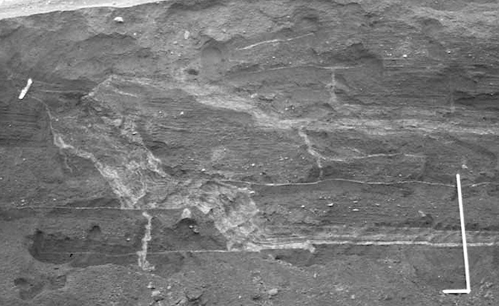
Subglacial dikes in Iceland. Sheeted dikes identical to those in the Touchet Beds were injected subglacially and interpreted as water escape structures triggered by ice loading. Water escaped out of the till into more permeable outwash below, partially following bedding. Myrdalsjokull forefield (Slettjokull), Iceland. Photo by Jaap van der Meer in Schomaker et al. (2010, Fig. 8.10).


Rubbly Injectites at Indian Creek, WA
In November 2017, I discovered several breccia-filled dikes that cut varved Glacial Lake Columbia beds along lower Indian Creek Rd (Hawk Creek) east of Lincoln, WA. They intrude sediments in response to subaqueous slumping of house-sized blocks of sediment. Glacial Lake Columbia was likely present at the time. The breccia fills are unsheeted and contain broken, stratified clasts of the host material. The dikes intrude the lower portion of the >20 m-thick section comprised of at least 24 rhythmites (alternating lake varves and flood sand intervals). In 2017, rotational slump blocks were exposed in fresh, recently-bladed slopes, but are now covered by erosion control matting and grass.


Field Work Matters
The origin of clastic dikes in sedimentary sequences can be ambiguous, especially at first glance. Earthquakes are not always required. In fact, clastic dikes occur in many settings where seismic shaking played no role whatsoever in their formation (Shanmugam, 2016). Lessons learned in coastal California or the Wabash Valley do not apply universally.
Clastic dikes are threshold features that, if interpreted one way, may prompt policy makers to brand a landscape hazardous and unfit for occupation or development. Interpreted another way, the same dikes become Ice Age relicts of little importance to anyone other than academics and megaflood enthusiasts.
Careful field work that involves a significant number of observations, measurements, samples. Perhaps most important is a study area properly scaled to the geological phenomenon at issue. Overuse of "seismite", shoddy field notetaking, and methods poorly suited to the region are unacceptable practices.
Project planning is the responsibility of the Field Geologist. The assisting Paleoseismologist should also be field-trained. Data gathered in the course of a paleoseismic investigation (fault slip rates, event dates, and shaking effects) are critical inputs to building codes, hazard planning documents, and land use policies. Data from the field certainly informs and often drives land use policymaking, which affects the lives of real people. Academics can sometimes lose track of the real world. Unlike esoteric articles and pretty tables of recurrence probabilities, maps constructed from field measurements are easily appreciated by all audiences. They are uniquely influential and tend to find their way into land use policy documents, which persist for decades.

Basic geometries of dikes in outcrop. Roadcuts rarely provide a complete view of dikes. Connections to source beds and pinchouts are commonly concealed. Reduce ambiguity by zeroing in on key geometries shown here. (A) Twin-tapering forms that do not look like typical dikes. They are axe blade-shaped fractures propagating laterally and emerging from the face of the outcrop. A trick of geometry in the third dimension (see Arris and Aperture figure earlier in article). (B) Three dikes that lack a taper direction are truncated at their tops by erosional surfaces (bedding contacts). (C) Buried sediment remobilized in response to shaking vents sand upward to a higher stratigraphic position (sill) or to the surface via a feeder dike (sand blow). May be sourced from above or below. (D) Upward and downward tapering dikes. Local shearing may have offset a single dike, causing it to appear as two with opposite tapers. A trick of limited exposure. Excavate features continue your search to find more conclusive relationships nearby. (E) Downward tapering dike-sill geometry with upward-curving intersections are sourced from above. (F) Upward tapering dike-sill geometry with upward (tree branch-like curving intersections are sourced from below.


Silt-sealed Cracks and Hydrofracture
Sand-propped hydraulic fractures are used to stimulate oil and gas reservoirs, a procedure commonly known as "fracking". Fracturing is induced by shutting in a portion of the well, adding a proppant slurry (sand + water + chemicals), and using pumps to jack up the fluid pressure until the formation yields. When the rock surrounding the well bore fails fluid-driven fractures propagate outward. The pressurized proppant slurry fills the expanding fractures and holds them open, permitting hydrocarbons to flow back to the well. The network of propped fractures exponentially increases the surface area of a well.
Unlike fracked formations at depths of hundreds to thousands of meters, the sediments that host the dikes are surficial deposits, unconsolidated and sandy that lack low-permeability layers that might act as a seal. Two key factors explain the formation of the dikes in Missoula flood deposits: high strain rate (rapid loading) and the rapid formation of silt skin walls on fracture walls (sealed pressure vessels).
Rapid loading - When loaded by a catastrophic flood, pressure in the shallow subsurface built so rapidly that hydraulic fracturing was induced. The normally loose (ductile) material failed in the brittle mode at the high strain rate. Pressure rose above that required for fracture and exceeded the sediment's capacity to dissipate pressurized fluid through its pore network. Rapid loading alone appears adequate to initiate fracture in a low tensile strength material with no true seal such as the Touchet Beds.
Silt skin walls - Once fractures began to form and fill, silt skin walls began to build. The sealing effect of the low-permeability skins delayed leakoff and facilitated further fracture. New fractures as well as natural flaws (cracks, soil macropores, burrows, etc.) provided low-resistance routes for new fractures to follow. Fractures immediately filled with sediment, the injected slurry (a natural proppant) sourced from within the overriding flood. Dewatering (leakoff), integral to the formation of the skin wall, begins the moment sediment enters a fracture. The skin-sealed crack begins to behave as a pressure vessel almost immediately. Pressure inside of the sealed fracture (pore fluid pressure, Pf) rises until it exceeds the confining strength of the material (Pf > 03) and the crack tip advances or, if leakoff loss exceeds Pf, the fracture closes. The fracture propagates in the 01–02 plane (vertical), widening against 03. As the fluid pressure equilibrates to the confining pressure (Pf = 03), the fracture tip halts, filling ceases, the crack closes down on its proppant, and pressure begins to build again if the load is still present. Each time Pf exceeds 03, the tip jumps forward or a new fracture initiates nearby. With each increment of widening, fluid pressure drops (volume increase = pressure decrease), but soon rebuilds. This loading-driven crack-fill-seal cycling created the dikes’ vertically sheeted fabric.


Evaluating Proposed Origins
In this section, I briefly evaluate seven proposed origins based on my observations and the literature.
(A) Desiccation hypothesis - Grolier and Bingham (1978) speculated that the dikes might be large mud cracks, filled by sediment that was blown in by wind or washed in by water. The idea was not revisited in subsequent reports by them or anyone else. Rightly so. Little evidence supports the dikes formed by desiccation. Their shape and nearly all internal characteristics are fundamentally at odds with the gravity-driven infilling of meters-deep cracks.
(B) Ground ice hypothesis - Many believe Eastern Washington's climate during the Last Glacial was 'periglacial' and the landscape was 'tundra'. But what do these terms mean? Periglacial is defined by the presence of ground ice (permafrost). Tundra by the absence of trees. Pleistocene paleosols are abundant in the region and indicate soils were never perennially frozen. There is no evidence permafrost or an active layer ever existed. Palouse soils contain abundant evidence of continuous life from ~2 Ma in the form of plant roots, rodent burrows, cicada burrows. Backfilled burrows in the Touchet Beds attests to rapid recolonization between outburst floods. No mention of relict soil wedges, frost stirring, or gelifluction is found in NRCS Soil Surveys for the Colville Indian Reservation (NRCS, 2002), Okanogan County (NRCS, 2010), Chelan County (USDA, 1975), Douglas County (NRCS, 2008), Grant County (USDA, 1984), or Lincoln County (USDA, 1981). Frost wedges in varved lake beds of the Glacial Lake Missoula basin (Chambers, 1984; Chambers and Currey, 1989; Levish, 1997; Hanson and others, 2012; Hanson, 2013; Smith, 2014, 2021) have not be found in the Channeled Scabland. Pollen samples from lake bottom cores indicate cold-tolerant plant species and conifers persisted during the Late Wisconsin (Blinnikov and others, 2002; Whitlock and Brunelle, 2006). Mammoth that roamed Columbia Basin were nourished by steppe-grassland forage, not tundra plants (Fry, 1969; Last and Barton, 2014).


(C) Lateral spreading hypothesis - Lateral spreading involves liquefaction at depth, horizontal block slides, and extensional cracking of the ground surface. The two figures below are classic examples of surface cracking resulting from spreading to a 'free face' (Cruden and Varnes, 1996). Cracks formed by spreading can fill with sediment and form dikes. Such dikes tend to parallel to the headscarp or nearby drainage. Steep-sided channels are not found in Touchet Beds sections and little evidence of low-angle sliding as depicted by Cruden and Varnes exists.


(D) Seismic shaking and liquefaction hypothesis - According to some, earthquakes along the Olympic-Wallowa Lineament created the clastic dikes in the Channeled Scablands. This requires the dikes to have formed by liquefaction, in whole or in part. The dikes are therefor feeder conduits to sand blows. However, the dikes bear no resemblance to liquefaction features described in textbooks (Allen, 1982; McAlpin, 2009), review articles on earthquake-caused soft sediment deformation (Dzulzynsky and Walton, 1965; Van Loon and Brodzikowski, 1987; Nichols and others, 1994; Obermeier, 1996; Montenat and others, 2007; Owen and others, 2011; Shanmugam, 2017), or >200 papers on liquefaction published in journals over the past two centuries. No liquefaction features have been found in more than a dozen seismic trenches excavated across active faults in Eastern Washington. Liquefaction-related clastic dikes in Washington have only been found in Holocene floodplain sediments west of the Cascade divide and fluvial-tidal deposits along Pacific beaches (Craig and others, 1993; Dickenson, 1997; Obermeier and Dickenson, 1997; Peterson and Madin, 1997; Atwater, 2000; Atwater and others, 2005, 2015).
(E) Flood-generated vibration hypothesis - The Missoula floods would have produced a tremendous rumble as they coursed through the landscape. The repeated cataclysms must have terrified humans and animals who witnessed their passage. The audible roar was likely accompanied by a vibratory resonance established in the bedrock and sedimentary cover, affecting broad areas beyond the advancing flood. Fracturing of sediment and bedrock by vibration is purely speculative as Icelandic jokulhlaups of the past century do not appear to produce damaging vibrations and no evidence of flood-related vibrations is known in geologic record of glacial regions more broadly. Research into seismicity generated by large floods is purportedly underway at Université de Grenoble-Alpes, France by Kristen Cook, Florent Gimbert, and Alain Recking.
(G) Hydraulic fracture triggered by floodwater loading (overloading) hypothesis - The field evidence is most consistent with rapid loading by cataclysmic floods. Fracturing and perhaps a bit of horizontal drag were triggered by the weight and velocity of the floods and slackwater lakes. Diking and flooding appear closely linked in time and space.


Conclusions
This article summarizes my work on sheeted clastic dikes in the Channeled Scablands over the past 30 years. I've documented and measured thousands of dikes at hundreds of outcrops throughout the floodway region. All of the dikes occur within the margins of Ice Age floodways and are identical with respect to size, shape, sedimentology, and age. All formed by the same mechanism: rapid loading and hydraulic fracture triggered by tsunami-like megafloods moving overland and ponding against bedrock constrictions for month-long periods. Deep, fast-moving floods and slow-draining slackwater lakes imposed enormous loads on sedimentary and bedrock substrates, opening wedge-shaped fractures that rapidly filled with sediment sourced from circulating bottom currents and the soupy lake bottom. Vertical sheeting, the result of crack-and-fill cycling, occurred during each flood event (producing compound dikes) and during successive flood events over time (producing composite dikes). Fluted skin walls, downward taper, and lack of a connection to underlying beds indicate dikes were filled from the top and leakoff began the instant sediment entered the fracture. The largest dikes occur where floodwaters were deepest and rhythmite stacks thickest. Dike widths scale with rhythmite counts and sheet counts. Unlike most clastic dikes in the literature, the features described here did not form by liquefaction or seismic shaking; they are not feeder conduits to sand blows. Clastic dikes in the Channeled Scablands are flood injectites, not seismites. This study confirms a hydrofracture origin (Pogue, 1998), validates most field observations by Jenkins (1925), Lupher (1944), and Black (1979), but rejects slumping (Baker, 1973), lateral spreading (Cooley et al., 1995), and lake drainage (Newcomb, 1962) as viable origins.
References
See THIS POST

This article expands on one I published in Northwest Geology v. 49 in August 2020. Northwest Geology is the yearly journal published by the Montana-based Tobacco Root Geological Society in conjunction with the TRGS field conference (www.trgs.org). Online version was first posted here 15 Sept 2020.
Keywords: clastic dike, sand dike, sand injectite, hydraulic fracture, Channeled Scablands, Missoula floods, megafloods, Columbia Basin, Cordilleran Ice Sheet, Touchet Beds
LAST UPDATED: Aug 2026


